How an Electric Generator Works
A petrol engine spinning one switchable magnet inside a ring of copper — and the moment you switch a light on, the shaft gets harder to turn.
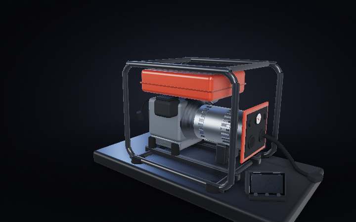
Step 01 of 08
The box that makes power
Petrol in the top, electricity out of the front. Between them sits an engine that is never allowed to change speed, and a drum of copper about the size of a coffee tin. Nothing on the outside tells you which half does what — and the half that actually makes the electricity is the quiet one.
Step 02 of 08
Two machines, one shaft
Take the covers off and there is nothing clever in between. No gearbox, no belt, no clutch. The engine’s crankshaft comes straight out of the back and bolts to the generator’s rotor through that flanged coupling — one shaft, one speed, no ratio anywhere. The engine’s entire job is to turn it at exactly the speed it is already turning. Everything that actually makes electricity happens inside the drum on the right.
Step 03 of 08
A magnet in a ring of copper
We have cut a wedge out of the drum. Inside: a ring of iron teeth packed with copper wire, sitting perfectly still — and spinning in the middle of it, a magnet. The two never touch. The gap between them is about half a millimetre, the thickness of a fingernail, and that gap is the entire machine. Every other part is only there to hold those two that far apart, that accurately, fifty times a second.
Step 04 of 08
Nothing happens until something changes
Copper sitting next to a magnet does nothing at all. Copper next to a magnet that is moving makes voltage — and that condition is fussier than it sounds. Watch the coils as the pole sweeps past. The one the magnet is pointing straight at goes dark. The bright ones are a quarter-turn away, off to either side, where the field threading them is swinging fastest. The voltage never came from the magnet being there. It comes from it leaving.
Step 05 of 08
Why it comes out as a wave
Each coil gets shoved one way as the north pole sweeps up to it, then the other way as the south pole follows it round. Wire the coils so those shoves add up and the output is a wave. Nobody designed that shape — it is just what a magnet going round in a circle looks like from the outside. One turn of the shaft, one full cycle. Which is why the engine is never allowed to speed up: 3,000 rpm is 50 hertz, 3,600 is 60, and a mechanical governor spends the machine’s entire life holding it there.
Step 06 of 08
Where the magnet gets its magnetism
The spinning part is not a permanent magnet — it is an electromagnet, which means its own current has to get aboard something already moving. Two brass rings on the shaft, two carbon blocks pressed down on top of them. Now look at what is NOT going through them: the power. All of that is made in the stator, which never moves, so these sliding contacts carry only the few amps needed to magnetise the rotor. A motor does it the other way round — it runs its entire current through a split ring, a commutator, and wears it out. This machine keeps its one rubbing part out of the main circuit altogether.
Step 07 of 08
Switch on a kettle, feel it in the shaft
Now actually draw some current. The moment it flows, the copper builds a magnetic field of its own — and it always points the wrong way, pushing back against the magnet that created it. The rotor gets physically harder to turn. The engine note drops, the governor opens the throttle, and the machine starts drinking more petrol. You are not collecting electricity that was already there. You are buying it, in torque, in real time.
Step 08 of 08
Sealed, spinning, holding 50 hertz
Bolt it back together and it is an orange box again, buzzing on its rubber feet. The three parts inside scale all the way up without changing: at a power station the rotor is a steel cylinder the length of a bus, the air gap is still measured in millimetres, and it still turns at exactly these 3,000 rpm. Almost every watt you have ever used came out of a machine shaped like this one.