How a Transistor Works
A whisper of base current controls a flood of collector current — the paper-thin N-P-N sandwich that switches and amplifies every circuit alive.
Step 01 of 08
1 · The component
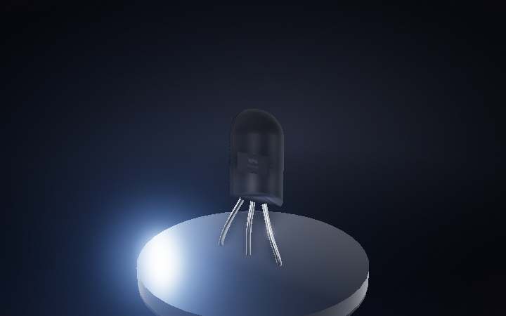
This is an NPN bipolar junction transistor in a TO-92 package — three legs (Emitter, Base, Collector) sealed in black epoxy around a sliver of silicon. It has no moving parts and stores no charge; its entire job is letting a whisper of current at one terminal control a flood of current between the other two.
Step 02 of 08
2 · Inside: the silicon die
Peel away the epoxy and the whole transistor is barely a couple of millimeters of silicon on a metal paddle. It is grown in layers: a wide N collector at the bottom, an almost paper-thin P base on top of that, and a small, heavily-doped N emitter diffused into just part of the base surface. Two gold wires the width of a hair carry the emitter and base connections out to the leads.
Step 03 of 08
3 · Two junctions, two different biases
Blow the die up to see the two junctions clearly. The base-emitter junction is forward-biased: that collapses its depletion zone to almost nothing, so current can cross easily. The base-collector junction is reverse-biased instead — its depletion zone stays wide, held apart by a strong internal field rather than conducting current the normal way. Watch both zones breathe as the bias sweeps on and off.
Step 04 of 08
4 · Injection: flooding the thin base
Forward bias floods the base with electrons injected from the heavily-doped emitter. They're now minority carriers in a p-type base too thin to recombine them all — most simply diffuse straight across before that can happen, and the reverse-biased base-collector junction's field sweeps them into the collector the instant they arrive. Only a small fraction recombine in the base; that trickle IS the base current.
Step 05 of 08
5 · Current gain: small controls large
Because almost every electron the emitter injects makes it across, a tiny base current sets the collector current almost entirely. The ratio is the current gain, β = Ic / Ib — commonly 50 to a few hundred for a small-signal part. Watch the base trickle complete one lazy lap for every several the collector stream races through: that speed difference IS β made visible.
Step 06 of 08
6 · The switch: cutoff vs. saturation
Drop the base voltage below roughly 0.6 V and the base-emitter junction never turns on — cutoff, no collector current, an open switch. Push it above that threshold and the transistor saturates: current gushes from collector to emitter almost unrestricted, a closed switch, lighting the lamp. Every logic gate in every computer ever built is transistors flipping between exactly these two states, billions of times a second.
Step 07 of 08
7 · The amplifier: a small wiggle, magnified
Bias it in between those extremes instead and the transistor stays in its "active" region, where collector current tracks base current smoothly rather than snapping between two states. A small wiggle riding on the base current comes out the collector as the same wiggle, scaled up by β — the mechanism behind every microphone preamp and radio receiver since the transistor was invented in 1947.
Step 08 of 08
8 · Doing its job, quietly
Reassembled, this is the same three-legged part scattered by the thousand across almost any circuit board — switching, amplifying, gating logic, never once touching a moving mechanical part. Just a whisper of base current, endlessly steering a flood of collector current.